
 English
 中文简体
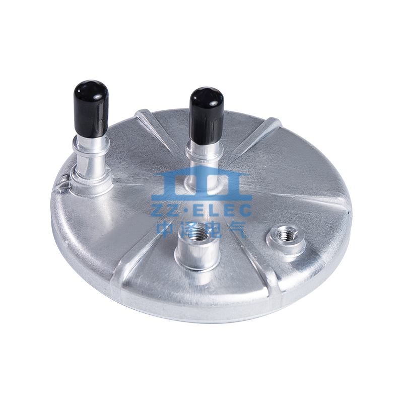
中文简体Fuel Filter Structure
Fuel filter cover&housingType: nearly every existingMaterial: AL1060We specialize in Aluminum cold extrusion. Fuel filter cover and housing could ...

Content
The capacitor case — the structural enclosure that protects a capacitor's internal dielectric, electrode, and electrolyte system from mechanical damage, moisture ingress, and thermal stress — has historically been treated as a commodity component in electronic and power engineering. That perception is changing rapidly in 2025. As capacitors are deployed in increasingly demanding environments — from fast-switching power electronics in electric vehicles to high-temperature industrial inverters, and from miniaturized medical implantables to grid-scale energy storage systems — the engineering requirements placed on the capacitor case have evolved from simple containment to a technically sophisticated functional component in its own right. Material innovations, precision manufacturing advances, and new failure mode data from field deployments are collectively redefining what constitutes best practice in capacitor case design across the electronics, automotive, energy, and industrial sectors in 2025.
The global capacitor market was valued at approximately USD 28.6 billion in 2024, with compound annual growth projections of 5.4–6.8% through 2029, according to industry tracking data from IHS Markit and IDC Electronics. The growth drivers span multiple technology transitions simultaneously:
Long-term reliability data from field deployments of capacitors in EV, solar, and industrial applications is generating new engineering insights that are directly influencing capacitor case design priorities. Failure mode analysis studies published in IEEE Transactions on Power Electronics and the Journal of Power Sources consistently identify three primary failure initiation sites in electrolytic and film capacitors:
These findings are accelerating investment in tighter manufacturing tolerances, improved sealing materials, and more sophisticated vent mechanism designs across the capacitor case industry.
Aluminum remains the material of choice for the majority of cylindrical electrolytic capacitor cases globally, accounting for approximately 70–75% of unit production across all voltage and capacitance ranges. The advantages that established aluminum's dominance — low density, high thermal conductivity, excellent deep-drawing formability, and natural oxide corrosion resistance — remain valid. However, the current generation of aluminum capacitor case production is incorporating significant metallurgical and processing advances that are improving performance at the margins where aluminum's limitations have historically been most problematic:
Polymer-based capacitor case constructions are gaining market share in specific application segments where aluminum's limitations — particularly galvanic corrosion in mixed-metal assemblies, electromagnetic shielding complications, and weight in mobile and aerospace applications — create genuine engineering constraints. The principal polymer case systems in commercial production include:
For high voltage capacitor case applications — typically above 1 kV DC in power electronics and above 400 V AC in motor run and power factor correction capacitors — stainless steel case construction (304 or 316L grade) provides the mechanical strength and pressure containment capability that aluminum cannot reliably deliver at elevated temperatures and internal pressures. Stainless steel cases with welded or hermetically sealed closures are standard in:
The pressure vent mechanism — the engineered weak point in the capacitor case that allows controlled pressure release before catastrophic case rupture in the event of internal failure — has become one of the most intensively developed aspects of capacitor case design in the current product generation. As capacitors are deployed at higher energy densities and in applications where case rupture would pose fire or explosion risks (EV battery packs, enclosed power distribution cabinets), the precision and reliability of the vent mechanism has become a primary safety specification:
The dimensional precision of a capacitor case directly affects the capacitor's electrical performance (case-to-winding fit determines internal pressure distribution and partial discharge behavior) and its reliability (dimensional variation in the case flange affects crimp seal quality). Key manufacturing quality parameters for precision capacitor case production include:
| Parameter | Standard Tolerance | Automotive/High-Rel Tolerance | Test Method |
|---|---|---|---|
| Case outer diameter | ±0.05 mm | ±0.03 mm | CMM / laser micrometer |
| Case length | ±0.1 mm | ±0.05 mm | CMM |
| Wall thickness uniformity | ±0.02 mm | ±0.01 mm | Ultrasonic thickness gauge |
| Roundness (circularity) | 0.05 mm max | 0.02 mm max | CMM roundness scan |
| Surface roughness (inner wall) | Ra ≤ 1.6 µm | Ra ≤ 0.8 µm | ISO 4287 profilometer |
| Leak test (sealed case) | Pressure decay method | Helium mass spectrometry ≤ 10⁻⁷ mbar·L/s | ASTM F2338 / MIL-STD-202 |
| Vent burst pressure accuracy | ±20% of nominal | ±10% of nominal | Hydraulic pressure test |
Capacitor case design and testing is governed by a layered set of international standards that define minimum safety and performance requirements across different application categories:
The relentless drive toward smaller, lighter electronic systems is placing increasing pressure on capacitor case designers to reduce case wall thickness and end-cap weight while simultaneously improving mechanical robustness and hermeticity. In aluminum electrolytic capacitor production, case wall thicknesses have reduced from the 0.5–0.7 mm standard of the 1990s to 0.25–0.35 mm in current production for standard voltage grades, enabled by improvements in aluminum alloy purity and deep-drawing process control. The next generation of ultra-compact designs targets wall thicknesses below 0.20 mm — a regime where grain structure, inclusion density, and forming lubricant chemistry all become critical process variables.
The European Commission's Battery Regulation (EU 2023/1542) and the forthcoming revision of the EU Ecodesign for Sustainable Products Regulation are introducing recyclability and material transparency requirements that will affect capacitor case material selection and marking. Aluminum cases have an inherent recyclability advantage — aluminum recycling recovers 95% of embodied energy versus primary production — but multi-material cases combining aluminum, polymer seals, and composite insulation sleeves require disassembly-for-recycling considerations that are increasingly being factored into new design programs.
In high-power-density power electronics modules, the capacitor case is increasingly being designed as an active thermal management component rather than a passive enclosure. Direct liquid cooling of capacitor cases — using brazed aluminum cooling plates integrated into the case structure — is entering commercial production in automotive DC link capacitor modules, enabling capacitor hot-spot temperatures to be maintained below 85°C in 150°C ambient environments and extending service life by a factor of 3–5× compared to passively cooled equivalent designs.
The most common material for a capacitor case is aluminum, used in the majority of cylindrical electrolytic capacitors due to its light weight, high thermal conductivity, and excellent deep-draw formability. Polymer materials — including PPS, LCP, and epoxy molding compounds — are used in film, ceramic, and SMD capacitors where electrical isolation and high-temperature performance are prioritized. Stainless steel is used in high-voltage and high-reliability capacitor cases requiring superior pressure containment and hermetic sealing. The specific capacitor case material is selected based on voltage rating, operating temperature, mechanical environment, and end-market certification requirements.
The vent mechanism in a capacitor case is a deliberately engineered weak point — typically a score groove or thin-section area on the case end-cap — that is designed to rupture at a controlled internal pressure before the case body itself fails. When a capacitor is exposed to abnormal operating conditions (overvoltage, reverse polarity, excessive temperature), internal electrochemical reactions generate gas that rapidly increases internal pressure. The vent allows this pressure to be released in a controlled, predictable direction, preventing explosive case rupture and reducing the risk of fire or secondary electrical damage. Vent actuation pressure is a critical safety parameter verified during both design qualification and production testing.
Capacitor case design affects reliability through several direct mechanisms. The seal quality at the case-to-terminal interface determines the rate of moisture ingress that degrades the electrolyte and shortens service life. Case wall thickness and alloy quality affect resistance to thermal fatigue cracking under high ripple current conditions. The precision of the case inner diameter determines the fit and contact pressure on the internal capacitor winding, which affects internal resistance and heat dissipation. In aggregate, case design and manufacturing quality account for an estimated 20–35% of electrolytic capacitor field failure events, based on failure mode analysis data published in IEEE TDEI and CARTS industry symposia proceedings.
Automotive-grade capacitor cases must satisfy AEC-Q200 stress test qualification, which includes thermal cycling (–55°C to +125°C or +150°C, 1,000 cycles minimum), mechanical shock (100G, 6ms half-sine), vibration endurance (20G, 10–2,000 Hz, 12 hours per axis), humidity-temperature cycling, and life testing at maximum rated temperature. In addition, IATF 16949 quality management system certification of the manufacturing facility and PPAP (Production Part Approval Process) documentation are required by most Tier 1 automotive suppliers and OEMs before approving a capacitor case supplier for production use.
A standard capacitor case — typically rated for operating voltages below 400V DC — uses deep-drawn aluminum construction with mechanically crimped end-cap closures suitable for the moderate internal pressures encountered in consumer and general industrial applications. A high voltage capacitor case — rated above 400V DC up to several kilovolts — requires heavier wall construction (0.5–1.5 mm versus 0.25–0.35 mm for standard grades), welded or hermetically sealed closures capable of containing significantly higher internal pressures, reinforced terminal insulation systems to prevent tracking and partial discharge at elevated voltages, and in many applications, stainless steel rather than aluminum case material to meet the mechanical strength requirements of high-energy storage applications.

Fuel filter cover&housingType: nearly every existingMaterial: AL1060We specialize in Aluminum cold extrusion. Fuel filter cover and housing could ...

After a quality assurance test, the response speed is faster, the price is lower, and it is easy to install.Material: Made of high-quality aluminum.
 7 (E65, E66, E67) Filter")
OE number:16126750475Representative models: BMW (Import) 7 (E65, E66, E67)

OE number:7H0127401DRepresentative models: VW import
 Z3 Filter")
OE number:13327512019Representative models: BMW (import) Z3

OE number:MANN: WK5015ZRepresentative models: BMW
 8 (E31), BMW (Import) 3 Compact (E36) Filter")
OE number:13 32 1 713 808Representative models: BMW (Import) 8 (E31), BMW (Import) 3 Compact (E36)
Copyright © Zhejiang ZZ Electric Co., Ltd. All Rights Reserved.
Custom Aluminium Cold Extrusions Manufacturers


